The System 4000
Installation and Service Manual
Controls Home | Systems Info | Latest News | Drawings | Helpful Files | Contact Us

Revised: January 31, 2012

PLEASE READ THIS MANUAL COMPLETELY
before attempting to install or operate the
SYSTEM 4000

Introduction... Multiple Operator Stations...
Description of System... Auxiliary Stop Inputs...
Description of Mode Selections... Holding Cam Adjustment...
Warranty... Brake/Motion Monitor...
Installation... Control Options...
Pulse Generator Assembly... Troubleshooting...
Operator Station/Guard Mounting... Parts Lists...

Introduction: Top

        The SYSTEM 4000 Stamping Press Control is designed to meet size and cost requirements for smaller size presses, yet can be used on any size pneumatic mechanical press, to improve press performance, reliability, and safety.
        The SYSTEM 4000 has been designed for highly reliable operation with long life while meeting or exceeding safety requirements by OSHA under regulations stated in Subpart 0, Sections 1910.212 and 1910.217 for mechanical power presses.
        The SYSTEM 4000 is a complete stamping press control system designed with dual-channel, self-checking circuitry. The solid state circuitry is low-current, highly reliable CMOS type with electric noise immunity built into all inputs. The compact size is ideal for smaller size presses such as the OBI type.
        Thoughtful setup, operation, and maintenance by you and persons working with you can insure your safety. Observe all the caution and warning labels in this manual, and warning labels on the equipment. They are intended to help you be safe and productive.
        An OSHA Compliance Guide can be purchased from Summers Press, Inc. at phone number 800-743-6491 or at their web site www.summerspress.com.


Description of System: Top

        The standard SYSTEM 4000 is capable of operating a part-revolution stamping press in nine different press modes. These modes include "INCH", "OFF", "SINGLE/GUARD", "SINGLE/FOOT-TRIP", "SINGLE/FOOT-HOLD-DOWN", "SINGLE/2-HAND", "CONTINUOUS/GUARD", "CONTINUOUS/FOOT", and "CONTINUOUS/2-HAND" press modes. See the next section for a description of each mode. All nine modes can be used, providing the proper safety devices and tripping methods are installed.
        One of the key features of the SYSTEM 4000 is that it is extremely easy to install and operate. The individually labeled, quick-disconnect terminals are labeled exactly as to each terminal connection (printed right on the circuit board). One terminal block is used for the 12Vdc connections and another for the 120Vac connections. All connections on the 12Vdc terminal block are in reference to common press ground.
        The Main Control Board can be quickly removed or replaced without removing any wire connections by simply unplugging the two terminal blocks and ribbon cable connector. Each wire remains securely fastened to it's appropriate terminal to eliminate confusion and save time.
        The press operator station, footswitch, guard, and auxiliary stop inputs are all low-voltage 12Vdc inputs for protection to the press operator. The two 120Vac clutch/brake outputs are controlled by solid state modules (field-replaceable) for long life and fast response times. Both clutch/brake outputs must be wired to a dual-solenoid valve for maximum safety.
        The basic control system contains two printed circuit boards in the main control console. These boards are the Main Control Board #554000E1A (revised March 2001) and the Door Interface Board #554260C1A (revised March 2000). The standard console size for the control system is 12" wide x 14" high x 6" deep as shown on the front of this manual (with some options).
The standard SYSTEM 4000 front panel contains the following:


Optional front panel components:


    H&W Controls manufactures our own labels at our facility per job requirement. .020 thick polycarbonate film is used for durability. The labels are scratch-proof/scuff-proof and easy to clean. This provides for easy customization to individual requirements at a fast turn-around time.
The standard SYSTEM 4000 will accept one press operator station containing two guarded "RUN" buttons, an "EMERGENCY STOP" button, and a continuous "ARMING/TOPSTOP" button. Extra "EMERGENCY STOP" buttons may be added in series with the included "EMERGENCY STOP" button per customer requirements. DO NOT ATTEMPT TO INSTALL MORE THAN ONE SET OF "RUN" BUTTONS TO THE STANDARD SYSTEM 4000. This will result in an unsafe condition. The "Multiple Operator Station/Multiple Guard Interface Board" #554850A1A must be installed to permit multiple operator station wiring. This board can be installed in the field in place of an existing or open Auxiliary Cam Board location (the mounting is the same). The basic SYSTEM 4000 was designed for only one set of "RUN" buttons for cost requirements necessary for smaller size presses.
    The SYSTEM 4000 receives the necessary signals for the built-in holding cams, auxiliary cams (if included), and built-in brake/motion monitor from the Pulse Generator Assembly #550750B2. The pulse generator is adjusted once at installation by rotating the shaft to the proper position and locking in place to the crankshaft via chain or coupler. The holding cam adjustment is then set inside the main control console (optional front panel adjustment may be included). Two sets of thumbwheel switches are used for the "Bottom Return" and "TOPSTOP" settings. The cams are set in one-degree increments from 0-359 degrees. Presses with variable speed adjustment require re-adjustment of the "TOPSTOP" setting with each change in press speed. The rotary switch adjustment in the SYSTEM 4000 provides a quick and easy way of re-setting both the press "BOTTOM RETURN" and "TOPSTOP" positions.
    The Pulse generator's pulse outputs are also used for the built-in motion monitor. The motion monitor will instantly shut off the clutch outputs if the ram (pulse generator shaft) stops rotating at any point during clutch engagement. This eliminates the need for a chain-break detection switch, which simplifies installation and reduces the size of the pulse generator assembly.
    Three "Auxiliary Stop Inputs" are included in the SYSTEM 4000. These include an immediate ram stop (existing to all versions Main Control Boards), continuous topstop, and PAUSE (added to the revised "D" version Main Control Board – March 2000).
    The PAUSE input now opens many windows for automatic-cycling presses and multiple press lines. Long feed lengths of any length can be easily integrated automatically to temporarily "pause" the ram until the feed is finished, then safely resume the cycle using just one signal. Also, multiple presses in a production line can be initiated using just one operator station. Each press is connected to the PAUSE input of the next press in line. All presses can be initiated together, but remain "paused" until the appropriate time. The presses will begin/resume motion when their "PAUSE" input is opened - providing any stop signal has not been previously initiated (guard interrupted, etc.).


Description of Mode Selections: Top

        INCH mode is used for setup purposes only. The motor may be on or off. Inching the ram while the motor and flywheel are slowing down (with the motor off) can permit accurate ram positioning on higher speed presses. Both RUN buttons must be pressed concurrently. The ram will continue to move as long as both RUN buttons are held down. The ram will stop at any point in the stroke if either RUN button is released. A switch is located on the Main Control Board for "INCH MODE AUTO TOPSTOP – REMOVE/ENABLE". See below…

        The INCH mode must not be used for production running!

        OFF mode inhibits any ram movement regardless of actuation method. The motor may be started and stopped in the OFF mode.

        SINGLE/GUARD (2-hand trip) mode can only be used if guarding is installed and closed or unobstructed. The motor must be running in the forward direction. Both RUN buttons must be pressed concurrently to trip the press. They may then be released immediately. The ram will continue for one full cycle as long as the guarding remains closed or unobstructed, and will stop at topstop position (position set by the holding cam TOPSTOP setting on the Main Control Board). As the ram reaches the bottom of the stroke (position set by the holding cam BOTTOM RETURN setting), the two holding cams will take over and bypass the guarding system during the upstroke. This enables parts to be removed more quickly while insuring safety.

        SINGLE/2-HAND (2-hand hold-down) mode can be used if no guarding is installed, or if the installed guarding is required to be bypassed*. The motor must be running in the forward direction. Both RUN buttons must be pressed concurrently and held down until the ram reaches the bottom of the stroke (position set by the holding cam BOTTOM RETURN setting). The holding cams will then take over and return the ram to the topstop position (position set by the holding cam TOPSTOP setting). If either RUN button is released during the downstroke, the ram will stop.

        * The guard may be active in the SINGLE/2-HAND mode, depending on the position of the "GUARD BYPASS SELECT" switch on the Main Control Board...

        SINGLE/FOOT mode is a guarded type mode (the footswitch can only be used in a guard type mode). The RUN buttons are inhibited in any FOOT mode (except in the INCH mode where the footswitch is inhibited). A guard must be installed and closed or unobstructed. The motor must be running in the forward direction. After each cycle, the footswitch must be released then re-depressed after the ram stops to initiate the next cycle. The SINGLE/FOOT mode can be used as "foot-trip" mode or "foot-hold-down" mode, depending on the position of the "SINGLE/FOOT MODE SELECT" switch on the Main Control Board...

        The standard Footswitch Assembly #500230A1 purchased from Brandes contains an added "kick-plate" in the back of the pedal for added safety (to prevent an accidental trip should something fall or press on the pedal while in the FOOT mode). The "kick-plate" must first be pressed inward before the pedal can be pressed. The footswitch assembly also comes complete with an eight-foot safety-orange rubber sealtite, ready to be connected to the SYSTEM 4000.

        CONTINUOUS/GUARD (2-hand trip) mode must be used with guarding installed and closed or unobstructed. The motor must be running in the forward direction. The ARMING/TOPSTOP button is first pressed momentarily to initiate a six-second arming timer. Both RUN buttons must be pressed concurrently during this period to trip the press. They may then be released immediately. The ram will continue in a continuous motion until the ARMING/TOPSTOP button is again pressed momentarily to stop the ram at the next topstop position. The guard is bypassed on every upstroke to allow for parts removal. The ram will stop immediately during the downstroke if the guard is interrupted. This mode is used normally for automatic-cycling presses.

        CONTINUOUS/2-HAND (2-hand hold-down) mode can be used if no guarding is installed, or if the installed guarding is required to be bypassed*. The motor must be running in the forward direction. The ARMING/TOPSTOP button is first pressed momentarily to initiate a six-second arming timer. Both RUN buttons must be pressed concurrently and held down during this period to keep the ram cycling in a continuous motion. If either RUN button is released during the downstroke, the ram will instantly stop. If either RUN button is released during the upstroke, the ram will topstop. This mode is used to monitor parts removal.
        * The guard may be active in the CONTINUOUS/2-HAND mode, depending on the position of the "GUARD BYPASS SELECT" switch on the Main Control Board.

        CONTINUOUS/FOOT mode must be used with guarding installed and closed or unobstructed. The motor must be running in the forward direction. The ARMING/TOPSTOP button is first pressed momentarily to initiate a six-second arming timer. The footswitch must then be pressed during this period and held down to keep the ram cycling in a continuous motion. The ram will stop immediately if the foot pedal is released during the downstroke. The ram will topstop if the pedal is released during the upstroke. The ram can also be stopped at the next topstop position by momentarily pressing the ARMING/TOPSTOP button while the foot pedal is depressed. This is a hands-free type cycle in which the operator must monitor parts removal - The ram can be quickly stopped by simply releasing the foot pedal.


Warranty: Top

        This product is warranted by H&W Controls to the original purchaser to be free from defects in material and workmanship under normal use for a period of one year from the date of purchase. If this product was purchased from H&W Controls by a qualified rebuilder or press manufacturer, this warranty will be forwarded as stated from the original date of purchase from H&W Controls to and only to the next purchased press user. During the warranty period, and upon proof of purchase, this product will be repaired or replaced (with the same or similar model), at H&W Control's option, at Henry & Wright Corporation, without any charge for either parts or labor. This warranty will not apply if this product has been miswired, misused, abused, or altered. All repaired products after one year from the date of purchase will be warranted by H&W Controls to the sender to be free from defects in material and workmanship under normal use for a period of 90 days from the date of repair. To obtain warranty service, you must take or send the product, postage paid, with the date of purchase or repair, to Henry & Wright Corporation. Due to the possibility of damage or loss, it is recommended when sending the product to Henry & Wright Corporation, that you package the product securely and send it insured, return receipt requested. NEITHER THIS WARRANTY NOR ANY OTHER WARRANTY, EXPRESS OR IMPLIED, INCLUDING ANY IMPLIED WARRANTY OF MERCHANTABILITY OR OF FITNESS FOR A PARTICULAR PURPOSE, SHALL EXTEND BEYOND THE WARRANTY PERIOD.         


Installation: Top

        The SYSTEM 4000 is the easiest stamping press control system to install and operate on the market today. A lot of care went into designing the SYSTEM 4000 to almost eliminate the need for interconnection drawings. Each terminal is dedicated to a particular purpose and clearly labeled for that purpose. Standard interconnection drawings are included in the back of this manual as guidelines for typical applications. Refer to these drawings as necessary. For special applications requested by the customer, modified drawings may be included separately. Be sure to follow these drawings and the drawings in this manual for a safe installation.

        AN IMPORTANT TIP... Never run any low-voltage DC wires in the same conduit or sealtite as high-voltage AC wires, unless the low-voltage DC wires are in shielded cable and the shield is grounded to the control cabinet (or any "Ground" terminal on 2TB).


Motor Control Packages: Top

        A motor control package may be included with the SYSTEM 4000, including a starter, disconnect switch, fuses, overload heaters, coil suppressors, control transformer, and/or a motor operator station on the SYSTEM 4000 front panel. The complete package may be prewired to the SYSTEM 4000 at H&W Controls, so all that is required by the customer is wiring in the motor and input voltage.
        Follow the motor control schematics in the back of this manual for interfacing to your existing or a new motor control. The same schematics are followed with prewired packages from H&W Controls for customer service requirements. Drawings are included for reversing and non-reversing motor controls, with or without different lube-motor styles, slide-adjust, and speed-adjust packages. All motor starter coils must be between 110 and 120Vac operating voltage!


Motor Control Connections: Top

        Use 1TB 4 and 1TB 5 for all motor control power connections. 1TB 4 and 1TB 5 supply the 120Vac to the motor starter circuits. DO NOT CONNECT ANY OUTSIDE POWER SOURCE TO THESE TERMINALS! The Main Control Board supplies the 120Vac voltage required to operate the motor control circuits via these two terminals.
        Use 1TB 6 and 1TB 7 to wire directly across the main motor forward coil (used as a reference of the main motor being on or off).
A four-wire interface to the SYSTEM 4000 is all that is required from/to the motor control circuit/s. Additional wires may be required for the motor operator station/s, if located on the SYSTEM 4000 front panel. See the motor control drawings in the back of this manual for reference.


Clutch Valve and Air Pressure Switch Connections: Top

        The SYSTEM 4000 is designed with dual-channel, cross-checking circuitry, and requires the use of a dual-solenoid safety valve of the proper air-line size for safe operation. The valve must have 120Vac coils. The size of the valve required should be stated in the clutch/brake specifications. The dual safety valve should be mounted as close to the clutch/brake rotary union as possible to permit the quickest exhaust time (3ft or less).
        The two main manufacturers of dual safety valves are ROSS Operating Valve Company and Herion USA, Inc.
        Henry & Wright Corp. recommends the Herion type XSz safety valve with the optional Pressure Switch Interlock Adapter #10-280-63. The Interlock Adapter mounts directly on top of the dual valve assembly and is internally connected to the valve air monitor ports. This air adapter monitors both the main air pressure (preset at 50psi) and the condition of the valve, thus eliminating the need for a separate main air pressure switch. If the air pressure drops below the set level, or if one side of the valve fails, the switch opens.
        The air pressure switch (Herion terminals 1 and 3) is wired directly to the air pressure switch terminals 1TB 8 and 1TB 9 on the Main Control Board. If a separate air pressure switch is used, connect the air-line to the input side of the dual valve at the main pressure (not to the output side to the clutch/brake). Wire the normally open contacts directly to 1TB 8 and 1TB 9. If a counterbalance air pressure switch or other is required, wire all pressure switch normally open contacts in series.
        The dual safety valve coils are wired to terminals 1TB 10, 1TB 11, and 1TB 12. The common side of both coils connects to 1TB 10. The other side of each coil connects to 1TB 11 and 1TB 12. See the motor control (120Vac) drawings in the back of this manual for details.

       
When connecting two dual safety valves (one for the clutch and one for the brake), and a delay for either or both the clutch or brake is required, the “Separate C/B Driver Board” #554270A__A is required. This board can be installed in the field after installation, provided an extra option board location is available (longer connection cables may be required; specify location when ordering). 
        When using the “Separate C/B Driver Board”, 1TB 11 & 1TB 12 on the Main Control Board remain open (no connections). Jumper 1TB 9 (on the Main Control Board) to 4TB 1, 4TB 3, 4TB 5, & 4TB 7 (on the Separate C/B Driver Board), if not already jumpered. Wire one side of the Brake valve coils to 4TB 2 & 4TB 4. Wire one side of the Clutch valve coils to 4TB 6 & 4TB 8. Connect the common of all four coils to any control common (1TB 10).
        When installing an electromagnetic clutch and brake, the “Separate C/B Driver Board” can be purchased with DC outputs. In this case, both clutch outputs and both brake outputs are wired in series to retain the control redundancy.
        As an option, physical switch inputs are provided at 5TB on the “Separate C/B Driver Board” which can be used to monitor the clutch and brake for absolute engagement and disengagement. If these inputs are not used, 5TB 1 and 5TB 2 must be jumpered together.


Pulse Generator Assembly: Top
Mounting and Adjustment:

        The Pulse Generator Assembly #550750B1 or #550750B2 is designed by H&W Controls to install on large and small presses with minimal installation.
        The pulse generator assembly contains a ¾" shaft which must be connected at a 1 to 1 ratio with the press crankshaft. The connection may be done by using a chain and sprockets, or by directly coupling the shaft using a flex-coupler to the press crankshaft or existing RLS shaft (if keeping for auxiliary cam purposes). Care should be taken not to exert too much side pressure on the pulse generator shaft, although, the shaft must be snug enough not to rotate under vibration (excess play could result in periodic brake faults when sitting idle).

Pulse Generator shaft adjustment ("B2" version):

        With the ram positioned at top-dead-center, the pulse generator shaft keyway is positioned (as shown on the side label of the PG assembly) at the 12:00 position in reference to the top of the pulse generator assembly. This is a one-time adjustment at installation. The keyway should be as close too top-dead-center as possible, but may be positioned slightly after top-dead-center to eliminate a periodical one-time "Motion Fault" at power-up. (At power-up, the SYSTEM 4000 may recognize a "Motion Fault" at the first clutch engagement, if the PG shaft keyway is less than 300 degrees before top-dead-center.)
Pulse Generator Dimensions

Pulse Generator Shaft Tightness Quick-Check... Top

        Occasional brake faults may occur if the chain or coupling to the pulse generator shaft is too loose or sloppy. A quick-check can be made to check the linkage for correct tightness...

BE EXTRA CAREFUL DURING THIS CHECK PROCEDURE. THE PROCEDURE REQUIRES THE CONTROL POWER TO BE ON.        

  1. At power-up (after all connections are verified), leave the motor shut off and make sure the flywheel is completely stopped.
  2. Press the RESET button to clear any fault conditions. Make sure the BRAKE/MOTION FAULT light on the control front panel is off.
  3. Place your hand on the pulse generator shaft and forcibly try to turn the shaft in both directions. If the BRAKE/MOTION FAULT light on the control front panel comes on, the shaft linkage is too loose or sloppy. Tighten up the linkage and repeat this procedure from step one. The linkage is tight enough when the BRAKE/MOTION FAULT light remains off.
  4. When using a chain and sprockets, repeat the above procedure at different areas of the cycle to make sure the sprockets are centered on both shafts, each time making sure first that the flywheel is completely stopped. Care should be taken not to exert too much side pressure on the pulse generator shaft, as this could result in shorter pulse generator bearing life.
Pulse Generator Connections:

        The Pulse Generator Assembly contains a solid state circuit board under the top lid (field-replaceable) which is accessible by removing the two Allen-head screws and lifting off the cover. With the cover removed, three LEDs are visible which indicate the three output statuses. The "D" version Main Control Board (revised May 2000) also contains LEDs above each input terminal on 2TB for PG output status without having to enter the pulse generator.
        The pulse generator assembly #550750B1 or #550750B2 contains a 15ft cable (standard) which connects directly to 2TB 1 through 5 in the SYSTEM 4000. The five conductor color-coded shielded cable connects to 2TB as shown below...

PG Terminal Description Wire Color 2TB (4000)
1 +12Vdc. Black 1
2 Ground White 2
No connection Shield Bare wire 2
3 "A" Pulse Red 3
4 "B" Pulse Green 4
5 Topstop sync Blue 5

        You may prefer to install sealtite around the pulse generator cable. In this case, the strain-relief connector can be removed from the pulse generator assembly and replaced with a ½" NPT standard sealtite fitting. Re-connect the cable as above between 2TB and the Pulse Generator Assembly. Be careful not to pinch any of the wires between the pulse generator cover and the pulse generator base when replacing the cover. Be sure to re-install the cover gasket to keep the inside dry and clean. See the interconnection drawings for 2TB in the back of this manual for more details.

Operator Station and Guard Mounting: Top

        When a fixed mechanical guard is installed, the distance from the guard to the die pinch-point (the closest pinch-point between the die and operator) is irrelevant, as long as the fixed guard prevents the operator from touching any part of the die. If the fixed guard is removable or opens for setup access, the moveable part must be interlocked to the SYSTEM 4000 (see "Guard/Light Curtain Connections").
        When a light curtain unit is used for guarding, the unit (transmitter and receiver) must be mounted at the MINIMUM SAFE DISTANCE from the die pinch-point area. The press operator station (both RUN buttons) must also be mounted at the MINIMUM SAFE DISTANCE, whether a light curtain is installed or not. Failure to do so may enable the operator to penetrate the die area before the ram has completely stopped, resulting in an unsafe condition.
        The MINIMUM SAFE DISTANCE (MSD) depends on the stopping time of the press. The stopping time is figured using a brake performance tester (such as the H & W Controls #BPT-3B), or, if the optional MSD/Stop Time Readout #554700A1A is installed in the SYSTEM 4000, the press can be cycled once to view the actual MINIMUM SAFE DISTANCE. To determine the MSD, the ram must be stopped at the 90-degree position (half way down) to determine the stopping time at the most dangerous part of the cycle per OSHA requirement.
        Once the stopping time is known (but the MSD is not), the MSD can be easily figured using the following formula...

Stopping Time (seconds) x 63 + 10% = MSD (inches)

The 10% in the formula is to allow for tolerable brake wear.

        The chart below may be used as an alternative to locate the MSD. Follow the correct stopping time up to the "MSD + 10%" line, then to the left to the actual distance in inches...

Typical MINIMUM SAFE DISTANCE Chart

        Be sure to mount all press operator stations (RUN buttons) and light curtains at or beyond the MINIMUM SAFE DISTANCE of the press. The MSD should be checked periodically (OSHA requires weekly checks) to verify the proper safety distance is less than that of the distance to all RUN buttons and light curtains on the press.

Press Operator Station Connections:

        The Standard Press Operator Station from H&W Controls #555010A1 consists of two guarded RUN buttons, an EMERGENCY STOP button, and an ARMING/TOPSTOP button. These four buttons contain low-voltage logic-reed contacts for optimal performance.
        Multiple Press Operator Stations #555011A1 may be included which require the use of the Multiple Operator Station/Multiple Guard Interface Board #554850A1A for proper operation. When installing multiple press operator stations, use the interconnection drawing #B554851A1 for wire connections, in the back of this manual. In addition to the components on a standard station, each multiple operator station includes extra contacts on both RUN buttons, an ON/OFF keyed selector, and an ON indicator light, which are required for multiple station wiring. For more information on the multiple operator stations, see the "Optional Multiple Operator Station/Multiple Guard Interface" section next in this manual.
        A Standard Press Operator Station #555010A1 is wired directly to 2TB 6 through 10 on the Main Control Board, as shown in the interconnection drawing #B554400D1 in the back of this manual.
        A Press Operator Station #555014A1 using Opto-Touch RUN buttons is wired directly to 2TB 1 and 6 through 10 on the Main Control Board, as shown in the interconnection drawing #B554400D2 in the back of this manual.
        Additional EMERGENCY STOP buttons may be wired in series with the EMERGENCY STOP button provided. Be sure to use low-voltage contacts on all EMERGENCY STOP buttons. All EMERGENCY STOP buttons must be wired to the "Emergency Stop" input at 2TB 9 on the Main Control Board. Do not use 2TB 16 ("Auxiliary Ram Stop") for EMERGENCY STOP buttons as this terminal is not an emergency stop input.
        
DO NOT WIRE MORE THAN ONE "RUN" BUTTON TO EACH OF THE RUN BUTTON INPUT TERMINALS ON THE MAIN CONTROL BOARD!        

        The standard SYSTEM 4000 is designed for a single set of RUN buttons to keep the size and cost down, and for simple installation and troubleshooting. Wiring more than one RUN button to each RUN button input will result in an unsafe condition. The SYSTEM 4000 contains anti-repeat circuits and timing circuits for each RUN button. These circuits will only function properly with one RUN button on each input terminal. (In the case of more than one RUN button installed on each terminal... If one RUN button or set of RUN buttons fails or is held down by some means, the control system would not detect an error. This would free an operator's hand or hands to penetrate the die area pinch-point during motion.)
        When more than one set of RUN buttons are required, use the Multiple Operator Station/Multiple Guard Interface Board #554850A1A. See the next section in this manual.

Optional Multiple Operator Station/Multiple Guard Interface: Top

        The Multiple Operator Station/Multiple Guard Interface Board #554850A1A must be used when installing more than one press operator station. Use only the Multiple Press Operator Station #555011A1 when installing multiple stations. Any number of multiple press operator stations may be installed and wired to the Multiple Operator Station Interface Board per drawing #B554851A1.

Each multiple press operator station includes:
        The Multiple Operator Station Board is used only for the RUN button wiring. The ARMING/TOPSTOP buttons are simply wired in parallel directly to 2TB 10 on the Main Control Board, and the EMERGENCY STOP buttons are wired in series directly to 2TB 9 on the Main Control Board.
        Each RUN button requires two contacts and are wired in series to the Multiple Operator Station Interface Board per drawing #B554851A1. This method permits any number of press operator stations to be wired safely.
        All FRONT operator stations must be connected to the "Front Stations ON" input terminal at 4TB 7 on the Multiple Operator Station Interface Board.
        All REAR operator stations must be connected to the "Rear Stations ON" input terminal at 4TB 8 on the Multiple Operator Station Interface Board.
        If/when ALL operator stations are turned OFF on one side of the press, that side becomes automatically guarded in ALL press modes (through the Multiple Operator Station Interface Board) using a light curtain mounted on that side of the press. This insures that that side of the press is protected at all times, since that side of the press is not in use. It is important that all front and rear stations are wired correctly to their corresponding "Stations ON" input terminal.
        If no REAR stations are installed, leave 4TB 8 empty. If no FRONT stations are installed, leave 4TB 7 empty.
        If multiple operator stations are often selected ON or OFF to accommodate different job setups, it is imperative that light curtains be installed on each side of the press that there are multiple operator stations installed – Even if the press will be cycling in a 2-HAND press mode. This will insure that each side of the press is protected no matter what stations are ON or OFF. The Multiple Operator Station Interface Board includes independent inputs for FRONT and REAR light curtains, which are gated internally with the FRONT and REAR operator station ON/OFF inputs.
        The FRONT light curtain is wired to the FRONT Guard inputs (Ch. #1 and Ch. #2) at 4TB 9 and 10, with the common of both channels wired to 4TB 11.
        The REAR light curtain is wired to the REAR Guard inputs (Ch. #1 and Ch. #2) at 4TB 12 and 13, with the common of both channels wired to 4TB 14.
        If no REAR operator stations are installed, and a fixed mechanical guard is installed on the REAR of the press, but the guard can be opened for setup purposes, the mechanical guard must be interlocked to the REAR guard inputs at 4TB 12 and 13 (install two limit switches on the guard to be used as interlocks). The REAR guard inputs 4TB 12 and 13 can be jumped to ground ONLY if the REAR side of the press is mechanically and permanently guarded or protected, and no REAR operator stations are installed.

DO NOT, UNDER ANY CIRCUMSTANCES, JUMP OUT THE GUARD INPUTS FOR A PARTICULAR SIDE OF THE PRESS, IF THERE ARE MULTIPLE OPERATOR STATIONS INSTALLED ON THAT SIDE OF THE PRESS THAT CAN ALL BE TURNED OFF!        

        * NOTE: Light curtains may not be required IF the press will be cycling ONLY in 2-HAND press mode, and one multiple operator station on each side of the press is permanently wired to be ON (the station ON/OFF keyed selector removed). In this case, jump the station ON/OFF inputs 4TB 7 and 8 to ground and leave the guard inputs at 4TB 9, 10, 12, and 13 open.
        When using the Multiple Operator Station/Multiple Guard Interface Board, wire the multiple operator stations and light curtains only per drawing #B554851A1. Do not wire any RUN buttons or light curtains/guards directly to the 2TB inputs. 2TB 7, 8, 11, and 12 must be wired only to the Multiple Operator Station Interface Board per the interconnection drawing.

Guard/Light Curtain Connections: Top

        The SYSTEM 4000 will only cycle in the GUARD or FOOT mode if a light curtain or mechanical guard is installed protecting the die area. Interlock switches on the mechanical guard or the output contacts of a light curtain must be interfaced to the "Guard" inputs at 2TB 11 and 12.
        The "Guard" inputs 2TB 11 and 12 on the Main Control Board are only designed to safely accept guarding on the FRONT side of the press. A FRONT and REAR guard must not be wired in series or parallel to the "Guard" inputs at 2TB 11 and 12. A REAR guard, if required, must be active in ALL press modes, and therefore, must be wired to the Multiple Operator Station/Multiple Guard Interface Board to utilize the individual FRONT and REAR "Guard" inputs - Even if only one press operator station is used. See the previous section in this manual.
        Do not use the Auxiliary Ram Stop input 2TB 16 for a REAR light curtain input. Although it seems this would work, 2TB 16 is not a dual-channel redundant input, as light curtains require for safe operation. 2TB 16 may be used to interlock a fixed mechanical guard on the REAR side when the guard needs to be opened only for setup purposes.

UNDER NO CIRCUMSTANCES SHOULD ANY GUARD INPUT BE JUMPED OUT! This would result in an unsafe condition.        

        
The GUARD inputs 2TB 11 and 12 are a single dual-channel input designed to accept the standard dual normally OPEN outputs from most light curtains. Both channel inputs must switch concurrently (within 20 milliseconds of each other) for proper operation. If both channels do not operate together, a MOTION FAULT will occur in the SYSTEM 4000.
        The normally OPEN light curtain output contacts should close when the light curtain is in the green state (powered up and unobstructed).
        H & W Controls recommends using the Dolan-Jenner Safescan 9 light curtain for direct connection to the SYSTEM 4000. The Safescan 9 does not require an external power supply or interface circuits and includes fixed and floating beam blankout. See drawing #B554400D1 or equivalent for light curtain connections.

SICKÔ Optic-Electronic Type FGS/MGS Light Curtain Interface:

        The SYSTEM 4000 is capable of accepting various types of light curtain systems, which are all wired to the "Guard" inputs on 2TB. Some light curtain systems require an interface circuit and others can be wired directly.
        The SICK
Ô Optic-Electronic Type FGS/MGS Light Curtain requires a 24Vdc power supply and interface, for proper operation. The #LCU-ACA Power Supply/Interface Board is available from SICKÔ Optic-Electronic for proper interface to the SYSTEM 4000. H & W Controls #565024A1A Power Supply/Interface Board is also available, and designed exclusively for interface to the SYSTEM 4000. Both interface boards will safely operate the FGS or MGS light curtain in the "Guard-only" mode, with automatic reset. Both interface boards also contain required "captive-contact" safety relays for safe operation. Below are interconnection drawings for both, the #LCU-ACA and #565024A1A Power Supply/Interface Boards.

Interface Board wiring for the SICK type FGS/MGS light curtain

SICKÔ Optic-Electronic Type AGS Light Curtain Interface:

        The SICK
Ô Optic-Electronic Type AGS Light Curtain can be directly interfaced to the SYSTEM 4000 "Guard" inputs. It's 120Vac power source can be connected to the control power transformer at 1TB 1 and 2. The light curtain is configured to operate in the "Guard-only" mode, as shown below in the interconnection drawing. At power-up, the light curtain must be reset to the "green" state by momentarily breaking the light beam. After this reset, the light curtain will operate as required. Use shielded cable for the low-voltage connections, from the output contacts to 2TB, to reduce electrical noise.

Interface Board wiring for the SICK type AGS light curtain

Footswitch Connections: Top

        The Footswitch Assembly #500230A1 may be included with the SYSTEM 4000 for hands-free cycling. The footswitch can only be used in the FOOT mode if guarding has been installed and interlocked to the "Guard" inputs 2TB 11 and 12. A footswitch may be added at anytime in-the-field.
        The H & W Controls footswitch assembly includes an 8ft prewired cable assembly for quick-connection to the SYSTEM 4000 "Footswitch" input at 2TB 14 and any "Ground" terminal.
        The Footswitch Assembly #500230A1 from H&W Controls contains a "kick-plate" in the back of the housing, which must be pushed inward before the foot pedal can be depressed. The footswitch is also fully shielded as a second precaution to accidental tripping.
        If a footswitch is obtained separately, the unit must be fully shielded to prevent accidental tripping. Use the normally OPEN contacts for connection to the Footswitch input 2TB 14 and 2TB 13 (ground).
        See Drawing #B554400D1in this manual for wire connections.

Auxiliary Stop Inputs: Top

        The SYSTEM 4000 includes three normally OPEN Auxiliary Stop inputs (two of which were added to the "D" version Main Control Board – March 2000). These stop inputs and descriptions are:

        The Auxiliary Stop inputs are low-voltage low-current inputs, which can safely accept hand-fabricated type sensors, if required. A metal rod or wire can be positioned over the steel stock to create a stock-buckle sensor (assuming the stock is grounded), for example. Use a "Ground" terminal (2TB 15) for the return wire, if using some other type of limit switch, sensor, or output from a monitor or protection device.
        Use only a dry-relay-contact or solid-state current-sync output from an outside device, to any of the Auxiliary stop inputs. Do not apply any outside power source to these terminals!

Control Power Connections: Top

        The SYSTEM 4000 is designed for a standard 120Vac power input, which is connected to 1TB 1 through 3 as shown below...

        The SYSTEM 4000 may include a motor control package which, upon request, may or may not be prewired to the SYSTEM 4000. The motor control package from H&W Controls includes a control transformer required for the 120Vac starters and SYSTEM 4000 power source. With the control transformer, the 3-phase 220/440Vac-power source for the motors is all that is required. A prewired motor control package is prewired to 1TB 1 through 7. No further connections are required to these terminals.

Before turning on the control power... verify ALL the connections with the installation drawings in this manual, and possibly, with custom drawings supplied separately by H&W Controls.        

Holding Cam Adjustment: Top

        Incorporated into the SYSTEM 4000 Main Control Board is two sets of rotary thumbwheel switches used for setting the HOLDING CAM ON (bottom return) and HOLDING CAM OFF (topstop) positions. These on-board adjustments from within the control enclosure eliminate the need to re-adjust RLS cams up high on the press, and provide an easy means of topstop re-adjustment for variable speed presses.
        The holding cam settings are adjustable in 1-degree increments from 0-359 degrees. Fault circuits are incorporated into the holding cam circuits to prevent the holding cam settings from being set too high, too low, or illogical. The ON setting must be set lower than the OFF setting. Other Fault circuits monitor the signals from the Pulse Generator Assembly and holding cam circuits for correct operation.
        The holding cam typical settings are as follows:
        The Holding Cam ON setting is used to set the point at the bottom of the stroke where the guard/s (if installed) become bypassed, and when the ram will continue automatically to topstop position.
        The Holding Cam OFF setting is adjusted to stop the press at top-dead-center position. The guard/s (if installed) will become enabled again at this point (if in a "Guard" or "Foot" mode.
        Two LED's are included on the Main Control Board, which monitor the holding cam circuits. The HOLDING CAMS ON LED (green) monitors the Ch. 1 and Ch. 2 holding cams. The HOLDING CAM FAULT LED (red) indicates either an incorrect HOLDING CAM switch setting, or bad or missing signals from the Pulse Generator Assembly. The "D" version and "E" version Main Control Boards also include LED's above each pulse generator input terminal on 2TB for pulse generator status.
        Optional front panel (external) Holding Cam switches may be included with the SYSTEM 4000 for easier and quicker holding cam ON and OFF adjustment. The front panel cam adjustments are set in the same manor as the on-board cam adjustments. The thumbwheel switches on the Main Control Board are not included when the front panel option is used.

Brake/Motion Monitor: Top

        The System 4000 Main Control Board contains a 360-degree Brake/Motion Monitor system. The independent Brake and Motion Monitors consistently monitor the clutch and brake through the entire stroke.

        The Motion Monitor is active while the clutch is engaged in the SINGLE and CONTINUOUS press modes. This monitor is bypassed in the INCH press mode to allow for slow "inching" of the ram while the flywheel is slowing down, if the motor is shut off (used mainly for setup on higher speed presses).
        The Motion Monitor is used to monitor ram movement while the clutch is engaged to protect the die, flywheel belts, and motor during a "stalled" condition by shutting off the clutch. A stall could result from a die jam-up, frozen bearing, low shut-height, etc. The clutch outputs are instantly shut off if the ram slows below 12/5 strokes-per-minute while the clutch is engaged.
        The Motion Monitor is also used to monitor the operation of the Pulse Generator. This eliminates the requirement of a chain-break switch on the Pulse Generator Assembly, since a motion fault will occur if the Pulse Generator stops during clutch engagement.
        The front panel Brake/Motion FAULT light coming ON and the main motor remaining ON distinguish a "Motion Fault".

Clutch/Motion Time Adjustment: Top

        The Motion Monitor's FAULT setting can be adjusted to either 12 or 5 strokes-per-minute by the MOTION TIME SELECT switch on the Main Control Board ("D" version – March 2000). Presses over 20 strokes-per-minute (spm) should use the right switch position "OVER 20 SPM" to provide a quicker response time. Presses under 20 spm should use the left switch position "UNDER 20 SPM". Presses under 8 spm may require a modified Main Control Board from H & W Controls. The standard SYSTEM 4000 Main Control Board will accept press speeds from 8 to 800 spm.
        The Motion Monitor circuit also monitors the clutch engage time of the press, and will shut off the clutch outputs if the clutch does not engage within a selected time period. This may occur with low air pressure or worn clutch plates, etc. Once motion begins, the clutch monitor drops out, and the motion monitor takes over. The Clutch Engage Fault time can be adjusted to either "1 second" or "350 ms" (milliseconds), by the CLUTCH TIME SELECT switch on the Main Control Board ("D" version – March 2000). Presses with a slow clutch engage time will require the left switch position ("1 second"). Other presses should use the right switch position ("350 ms") to provide a quicker response time in shutting off the clutch outputs.

        The Brake Monitor is required by OSHA to monitor the stopping time of the brake during clutch disengagement, and inhibit further operation if the safe stopping time is exceeded. A faulty or worn brake could allow the operator to penetrate the die pinch-point area before the ram comes to a complete stop.
        The H&W Control's Brake Monitor continually monitors the brake in ALL press modes, during and after every clutch disengagement through the complete 360-degree cycle. The only time the brake monitor is not active is while the clutch is engaged.
        The front panel Brake/Motion FAULT light coming ON and the main motor shutting OFF distinguish a "Brake Fault".
        The brake monitor's stop-time adjustment is adjusted with the ALLOWABLE STOPPING TIME potentiometer on the Main Control Board. If this time adjustment is set too low, or the set stop-time is exceeded, a BRAKE FAULT will occur at clutch disengagement. See the next section on "Stopping Time Adjustment".
        A TEST button is included with the SYSTEM 4000 used to test the Brake Monitor and outputs to the clutch and motor control. When the TEST button is pushed the clutch (if engaged), and all motor control should turn off, and the Brake/Motion FAULT light on the control front panel should light and remain lit. Push the RESET button to clear any faults or tests.
        The Brake Monitor contains self-checking circuitry, which momentarily flashes the Brake/Motion FAULT light on the control front panel, during each clutch disengagement. During this momentary flash, the brake monitor is comparing the stop time of the press with the ALLOWABLE STOPPING TIME adjustment. The next cycle is inhibited until this flash ("check") is completed, to allow the brake monitor to fully function. Turning the ALLOWABLE STOPPING TIME adjustment up higher than is required, will prolong the cycle inhibit, and hence, decrease production. If the press stop-time is within the ALLOWABLE STOPPING TIME adjustment, the Brake/Motion FAULT light will go back off, enabling the press to be re-cycled. Bottom line... The ALLOWABLE STOPPING TIME adjustment should be set as low as possible, without creating a Brake Fault.
        A brake fault WARNING indication is included on the "D" version Main Control Board (March 2000). If the press stop-time is within 2-degrees of a BRAKE FAULT, the Brake/Motion FAULT light on the control front panel will continually "blink" on and off after the "check" period at each clutch disengagement. This is only an indication of a near Brake Fault, and the press will still cycle as normal.

Stopping Time Adjustment: Top

        Use the ALLOWABLE STOPPING TIME potentiometer on the Main Control Board to adjust the stop-time allowed, before a Brake Fault occurs. Set the "Allowable Stopping Time" as follows…

        When adjusting the ALLOWABLE STOPPING TIME, the press is disengaged at the 90-degree crank position, which is usually the point of the longest stop-time.
Continued use of any press will eventually cause an increase in stopping time as the brake linings wear, or the springs weaken. If BRAKE FAULTS eventually start to occur, it is wise to first check the brake assembly and linings, before simply increasing the ALLOWABLE STOPPING TIME setting. After all, the whole reason for the brake monitor is to monitor the brake!

Brake Monitor Testing Procedure: Top

        At the beginning of each shift, verify proper Brake Monitor operation by performing the following tests…

  1. With the press stopped, push the TEST button. The front panel "Brake/Motion FAULT" light must light and remain lit, and the motor must shut off. Attempt to start the press – It must not start.
  2. Push the RESET button. The front panel "Brake/Motion FAULT" light should go off. The motor can be restarted.
  3. With the press cycling, push the TEST button. The press must stop and the motor must shut off. The front panel "Brake/Motion FAULT" light must light and remain lit.
  4. Push the RESET button. The front panel "Brake/Motion FAULT" light should go off. The motor can be restarted, and the press can be recycled.

Optional - Auxiliary Cams: Top

        The Auxiliary Cam Boards #554900A1A and #554900A2A are designed for the SYSTEM 4000 auxiliary cam requirements. The standard 12" x 14" control enclosure can accommodate one Auxiliary Cam. Up to 10 Auxiliary Cams may be used in the SYSTEM 4000, using larger enclosures.
        Each Auxiliary Cam is adjusted with thumbwheel switches, in the same manor as the Holding Cams on the Main Control Board. Adjustment is set in one-degree increments, from 0-359 degrees. Separate settings control the cam ON and cam OFF positions. Each cam board will operate one ON/OFF transition per stroke. Accuracy is better than 2-degrees. Making sure the SYSTEM 4000 Pulse Generator shaft keyway is adjusted exactly as specified can optimize the accuracy of the cam settings.
        As with the Holding Cam settings, FAULT check circuits are incorporated into each Auxiliary Cam Board. If a cam fails, the ram will be stopped and inhibited until RESET. Circuits are also included, to prevent the cam settings from being set too high or illogical. The ON setting must be set at least 2-degrees lower than the OFF setting on each cam board. Each cam board must turn on and turn off every press stroke, or the cam will FAULT. "FAULT" and "Cam ON" LED's are included on each cam board for easy identification.

        The Auxiliary Cam Board #554900A1A is a relay-output version Auxiliary Cam. Each cam board contains 1-N.O. and 1-N.C. isolated output contact, capable of 120Vac at 3 amps maximum. Surge suppression and arc protection are built into each cam board for long contact life and low electrical noise. The N.C. output contact can be used when a cam is required to be closed over top-dead-center. The ON and OFF settings are then set in reverse (since the ON setting must be set lower than the OFF setting).
        Example: To turn a cam ON at 270 degrees and OFF at 45 degrees… Adjust the ON setting to 045 and the OFF setting to 270, then use the N.C. output.

Auxiliary Cam/s Output Configuration

        The Auxiliary Cam Board #554900A2A is a solid-state-output version Auxiliary Cam with a 12Vdc-sourcing output. This version is recommended for interfacing to electronic feed systems, or PLC inputs, since any contact "bounce" is eliminated. TB1 and TB2 terminals are not used in this version. Use terminals 3 (output) and 4 (ground) only.

        Installation of each Auxiliary Cam requires the 1RC ribbon cable to be plugged into the 1RC socket on the Main Control Board, or preceding Auxiliary Cam Board. The Door Interface Board 1RC ribbon cable plugs into the last Auxiliary Cam Board on the left. The blue wire at the bottom of each Auxiliary Cam Board (Topstop Sync) must also be plugged into 2TB 5 on the Main Control Board, or daisy-chained over to the next Auxiliary Cam Board "Topstop Sync" terminal. If the blue wire is not connected to one or more Auxiliary Cam Boards, the unconnected boards will FAULT at the first topstop position.

Optional - 6, 12, 18 Channel Die Monitoring: Top

    The optional 6-channel Die Monitor Board #554950A1A can be used with ALL version System 4000 Main Control Boards through the "E1" version. Use the Die Monitor Board #554950A2A with the "E2" version Main Control Board. The mounting holes are identical to the Auxiliary Cam Board mounting for easy installation or upgrade. Up to three Die Monitor Boards may be used providing a total of 18 die-monitoring channels.
    Also available is the Die Monitor Indicator Board #554955A1A which provides 6 remote (front panel) FAULT lights. The Indicator Board plugs into the remote indicator socket provided on the Die Monitor Board. The Die Monitor Board can be used with the Remote Indicator Board, or as a stand-alone internal die monitor. The Die Monitor Board contains on-board FAULT LEDs for internal visual fault indication when the Remote Indicator Board is not included.
    Each Die-Monitoring channel can be programmed as required for "Immediate Stop", "Topstop", or "Cyclic" sensing, and monitored either "Inside Window" or "Outside Window". A "Window" input is included with each channel which may or may not be used depending on the application. When required, a "Window" input may be wired directly to an available Auxiliary Cam Board for easy and accurate window adjustment. 
    A "Window" input is used when its sensor must only be "seen" during a portion of the press cycle, and ignored during the rest of the cycle. The "Inside Window / Outside Window" switch can reverse the effect of its "window" input just as switching the contact of the "Window" input cam from normally open to normally closed. 
    All sensor and window inputs are low-voltage, low-current, current sync type which can accommodate most types of sensors including hand-fabricated designs. All inputs on this board are "made" when touched to press ground or one of the "Ground" terminals provided. Outputs are provided with +12Vdc reference voltage required for use with proximity type sensors (current-sync type - 200 milliamps max.). As in a typical case with "Stock Buckle", a sensor input can be wired directly to a steel bar or grid just above the stock (isolated from press ground) with a single wire. If the conductive stock touches the grid, a "Stock Buckle" fault will occur. In this case, the corresponding channel program switch would be set to the "Stop" position (left) to enable an immediate stop condition when the fault occurs. 
   
When a fault occurs on any channel, the press will stop or topstop (depending on the selection), and lock out until reset by the control RESET button. The corresponding Fault LED on the Die Monitor Board will light and if included, the remote front panel Fault light will light. Further press operation will be inhibited until reset.

  NOTE: If the "Stop" position is selected on a particular channel, and its sensor remains closed indefinitely, the control will not reset (the fault LED and light will remain lit and operation inhibited) until the sensor is opened.   

    Some typical connections to the Die Monitor Board are shown on the Interconnection Drawing #B554950A1 in the back of this manual. 

OptionalSeparate Clutch & Brake Valve Connections with Adjustable Delays:

Top

When separate air valves with time delays between them are required for the clutch and brake, the “Separate C/B Driver Board” #554270A1A is required. This board contains four output modules (two for each the clutch and brake) with individual LED indicators and individually fused and suppressed for protection.
            This board provides solid switching of the clutch and brake valves, with an adjustable time delay for “Clutch Engagement” and for “Apply Brake” of 0 – 300 milliseconds each.
            A 500 millisecond auto-cutoff is incorporated into the brake circuit for added safety, in case of any failure. If this failure should occur, the “Brake Engage Delay Fault” LED will light and prevent any further press operation until reset.
            A “Delay Mode” switch is included on the “Separate C/B Driver Board” to allow “Delay Always” or “No INCH Delay”. When the control is placed in INCH Mode, the delay between the clutch and brake will be automatically removed when “No INCH Delay” is selected and the clutch and brake will work concurrently as if parallel wired.
            As an option, inputs are provided at 5TB for connection to physical switches which monitor the clutch and brake for absolute engagement and disengagement. These inputs can be used in conjunction with the time delays if desired; otherwise both time delays are set to “0”. LED’s are included above each switch input to monitor switch activity. If these switch inputs are not used, 5TB 1 and 5TB 2 must be jumpered together. See Drawing #B554270A for details.


Optional - Production Counter: Top

        A Production Counter may be included on the SYSTEM 4000 front panel. The counter is prewired at H & W Controls, to the Door Interface Board 1PL Connector. The counter will advance one count each press cycle at the Holding Cam OFF (topstop) setting. This counter is automatically bypassed in the INCH press mode.
        The current count can be read with the control power on or off. The counter operates on it's own internal lithium battery, which prevents a reset from occurring if the control power fails. The counter battery life is approximately six years.
        A keyed RESET button is included to prevent unauthorized resets. Count range is to 999,999. See Drawing #B554600D1 in this manual for wire connections.

        NOTE: Electrical noise generated in the control may cause the production Counter to count erratically. This noise is usually caused by not suppressing ALL motor starter coils connected to the SYSTEM 4000. Suppression is used on ALL starters that H & W Controls provides.

Optional - Auxiliary Light Outputs: Top

        The SYSTEM 4000 can provide external terminal connections for the five front panel Indicator Lights. These five external connections can be used to directly operate a 12Vdc-relay coil or indicator light (200-mill maximum each) for remote status indication.
        SYSTEM 4000 controls with the "A" version Door Interface Board #550260A1A must use the optional Auxiliary Light Output Board #550300A1A to provide these remote terminals. The Auxiliary Light Output Board is simply connected in series with the 1RC ribbon cable.
        SYSTEM 4000 controls with the "C" version Door Interface Board #554260C1A (March 2000), include these five terminals (including a common "Ground" terminal) on the Door Interface Board.

        Auxiliary light output descriptions:

Optional - MSD/Stop-Time Readout: Top

        The SYSTEM 4000 may include a field-selectable MINIMUM SAFE DISTANCE or STOP-TIME display readout on the control front panel. This readout is updated at every clutch disengagement.
        When the MSD/Stop-Time Display Readout is mounted on the control front panel (for external viewing), a small black selector switch is mounted on the rear side of the board for easy access from inside the enclosure. This switch selects either MINIMUM SAFE DISTANCE (MSD) or STOP-TIME readout. When viewing from the rear side, selection is as follows...
        In the MINIMUM SAFE DISTANCE mode, the decimal point is lit. The display will read the press actual MINIMUM SAFE DISTANCE in tenths of an inch increments, up to 99.9 inches. All press operator stations and light curtains must be mounted outside this MSD reading.
        In the STOP-TIME mode, the decimal point is off. The display will read the press actual "Stop-Time" in milliseconds, up to 999 milliseconds (1 second). If you multiply this reading (".???") times 63, you will end up with the same reading obtained as if in the MSD mode.

        
A "Limit Exceeded" LED is included, which will light if the Stop-Time or MSD reaches it's maximum limit. The limit for stop-time is 999 milliseconds. The limit for minimum safe distance is 99.9 inches.
        A "TEST" LED is included, which will light while a TEST is being performed in the MSD/Stop-Time Readout Board (by pushing the "Brake/Motion TEST" button). See below.

MSD/Stop-Time Readout Calibration TEST:
        If the display does not count up to "63.0" (62.9 – 63.1 is ok), disregard any display readings, and have board serviced at Henry & Wright Corp. The MSD/Stop-Time Readout Board can be removed for repair in a couple minutes, without any effect on the SYSTEM 4000 operation. With the power off, gently unplug the 2RC-ribbon cable from the 2RS-socket on the Door Interface Board, by pulling straight out from the socket (A slight rocking motion helps prevent any pins from bending or braking off while unplugging).

Optional - Crank Position Readout: Top

        The SYSTEM 4000 may include Crank Position readout on the control front panel. This readout is used for determining the crank (ram) position in the cycle, in degrees. "000" and "360" are top-dead-center position (depending on which direction the press is cycling). If the press direction reverses, the count direction will reverse also, keeping the correct crank position.
        Accuracy in the Crank Position readout is less than 2-degrees, if traveling in one direction only. If the crank is reversed during a stroke, the accuracy drops to about 4-degrees within the same stroke. It is best to cycle one complete stroke in the same direction before using the readout for precise positioning. It is possible that, if the counterbalance is not adjusted properly, the crank could briefly reverse direction at clutch engagement. This would cause the Crank Position readout to briefly reverse direction, thus, reducing the accuracy slightly.
        The correct mounting position of the Pulse Generator shaft keyway is very important to obtain an accurate Crank Position readout. Make certain that the keyway is at exactly 12:00 (in reference to the top cover of the Pulse Generator Assembly), with the ram at top-dead-center position. The "A2" Pulse Generator Assembly cannot be used with the Crank Position Readout. Use the "B2" version Pulse Generator Assembly (#550750B2) only.
        Two LED's are included in the Crank Position display for indication of FORWARD or REVERSE crank direction. This provides an easy view if the crank unintentionally reverses direction. When production running, the FORWARD LED should be lit only, without any occasional flickering.
        A "Fwd/Rev" output is provided at TB6 for special interfacing requirements. This current-sync output is normally at 12Vdc in the forward direction, and is pulled low while in the reverse direction (40 mills maximum).
        Depending on the direction of the crankshaft, the Crank Position display will count up or count down. When the press is moving in the forward direction, the Crank Position display should count UP. A selector switch is provided at the bottom of the Crank Position Readout Board for "PG Shaft Rotation". This switch is placed in the "Clockwise" or "Counter-Clockwise" position to change the count direction per Pulse Generator installation direction. Switching this switch, will cause the Crank Position display to count UP or DOWN per installation requirement.
        The Crank Position Readout Board is wired directly to the outputs of the Pulse Generator Assembly. A five-wire cable is connected between 2TB 1 through 5 on the Main Control Board, and TB 1 through 5 on the Crank Position Readout Board.

Troubleshooting the SYSTEM 4000: Top

        The SYSTEM 4000 is designed to be very easy to troubleshoot and repair with minimal downtime. The front panel indicator lights, and LED's on the Main Control Board and Door Interface Board can be used to instantly identify the problem. The front panel indicator light sequence is described as follows...

        POWER ON light - Monitors the 12Vdc power source on the Main Control Board. This light should be lit as long as power is applied to the system. The "D" version and "E" version Main Control Boards also contain a 12Vdc indicator LED above 2TB 1.
  1. Check fuse F2 on the Main Control Board.
  2. Check for 120Vac between 1TB 1 and 1TB 2 on the Main Control Board.
        GUARD light - Monitors the "GUARD" inputs at 2TB 11 and 2TB 12. This indicator light remains lit in the INCH and 2-HAND modes, and during the holding cams (up-stroke), regardless of the condition of the "GUARD" inputs. Keep in mind that the guard is bypassed during the holding cams, which are adjustable by the "HOLDING CAM SETTINGS" on the Main Control Board. Setting the Holding Cam ON (bottom return) position too low will bypass the guard completely. The Holding Cam ON (bottom return) position is inhibited from being set below 100 degrees. The setting is recommended to be set above 160 degrees.
        MOTOR FWD light - Lights when the main motor is running (in the forward direction). The press will not cycle in any mode except INCH, if the main motor is off (MOTOR FWD light not lit).
        CLUTCH ENGAGED light - Should light whenever either or both clutch outputs are on. (Both outputs must turn on to cycle.)
        BRAKE/MOTION FAULT light - Lights whenever a brake or motion fault occurs. The difference in faults is easy to distinguish... If the main motor remains running, the fault is a Clutch/Motion Fault. If the main motor shuts off, the fault is a Brake Fault. A brake fault will occur at clutch disengagement, and a clutch/motion fault will occur at or during clutch engagement. (The Clutch/Motion Fault circuit is bypassed in the INCH press mode, to allow for slow inching of the ram with the motor off.)
        On the "A" or "B" version Main Control Board... Cut resistors R23 and R24 that are extending out from the board (above the "Holding Cam ON" switches). Do not cut the R23 and R24 resistors that are against the board!
        On the "D" or "E" version Main Control Board... Switch both the "Clutch Time Select" and "Motion Time Select" switches to their left positions.

Status and Fault LED's: Top

        LED's are provided on the Main Control Board to monitor the holding Cam circuits. A "HOLDING CAMS" LED (green) is lit during the holding cams (upstroke). "Holding Cam FAULT" LED's (red) provide indication of a pulse generator Fault, or incorrect holding cam settings.
        The "D" version Main Control Board #554000D1A (released March 2000) or #554000E1A (released March 2001) contains status LED's above each terminal on 2TB and 1TB for an easy view of operating status. These high-speed LED's monitor all inputs and outputs, and eliminate the need for a voltmeter. The LED's above 2TB 1 through 2TB 5 monitor the entire pulse generator assembly, thus eliminating the need to open the pulse generator cover.
        The "C" version Door Interface Board #554260C1A or #554260C2A (released March 2000) also contains a chart of status LED's monitoring both mode selector switches and the TEST and RESET buttons. This provides a clear indication of the actual (electrically connected) PRESS and OPERATOR modes.
        With both new version boards combined, virtually All inputs are monitored and easily viewed for fast troubleshooting.

Quick-Disconnect Terminal Blocks: Top

        The SYSTEM 4000 is designed to be quickly serviced, by providing quick-disconnect connectors on all circuit boards. The Main Control Board contains three connectors which are unplugged to remove or replace the board. All wires connected to 1TB and 2TB remain connected to their appropriate terminals. The complete terminal blocks are simply unplugged from their sockets, by pulling them straight out. The 1RC ribbon cable is unplugged by first, moving the rubber hold-down strap to the side, then unplugging the connector. Care must be taken on the "A", "B", "D1", or "E1" version Main Control Board (with the 16 pin RC connector), that the plug is gently pulled straight out from the socket, so the pins do not bend or break off. The "E2" version Main Control Board uses a 20 pin break-proof connector, which is not interchangeable with the "A", "B", "D1" or "E1" versions.

SYSTEM 4000 Troubleshooting Guide: Top

        CAUTION: The outlined area around 1TB on the Main Control Board contains 120Vac. Use caution when working in this area with power on.

        WARNING: Do not touch any part of any circuit board with a metal object while power is on. This could damage the integrated circuitry and void warranty. Use caution when working around and in the control cabinet.

        The following troubleshooting guide must be read from the beginning, so that any steps are not overlooked. Locate the first problem described in the guide that you observed on your press...

Main motor does not start:
  1. Check for 120Vac power input voltage at 1TB 1 and 1TB 2. The POWER ON indicator light should be lit.
  2. Check fuses F1 and F2 on the Main Control Board.
  3. Relay REL 1 (MOD 1 on the "D" or "E" version Main Control Board) must be energized.
  4. The front panel "Brake/Motion FAULT" light must be OFF. Reset all faults.
  5. The "Emergency Stop" input at 2TB 9 must measure 0Vdc to ground. Check all EMERGENCY STOP buttons normally closed contacts. The "D" or "E" version Main Control Board contains a fault LED above 2TB 9, which should be off.
  6. Check the main motor starter overload heaters and motor control wiring.
  7. Check the "Air Pressure Switch" input terminals at 1TB 8 and 1TB 9. They should be shorted together through the pressure switch/es (120Vac on 1TB 9). The "Air Pressure OK" LED should be lit above 1TB 8 and 9 on the "D" or "E" version Main Control Board.
Press does not cycle in INCH press mode:
  1. Check RUN 1 and RUN 2 button inputs at 2TB 7 and 2TB 8. Each should normally measure 12Vdc, and go to 0Vdc when that button is pressed. The "D" or "E" version Main Control Board contains status LED's above both input terminals.
  2. Check the "Auxiliary Ram Stop" input at 2TB 16. It should measure 12Vdc (normally open). If not used, leave open. The "D" or "E" version Main Control Board contains a fault LED above 2TB 16.
  3. The front panel "Brake/Motion FAULT" light must be off. Reset all faults.
  4. Check the "Holding Cam FAULT" LED on the Main Control Board. It must be off.
  5. Make sure the PRESS MODE keyed selector is in the INCH mode. The blue wire on the PRESS MODE selector must be 0Vdc, and the green and yellow wires at 12Vdc. The "C" version Door Interface Board - March 2000, contains a chart of status LED's to monitor all modes. The INCH mode should be lit.
If the front panel "CLUTCH ENGAGED" light lights when the RUN's are pressed, but does not engage the clutch...
  1. Check fuse F3 on the "A" or "B" version Main Control Board, or the fuses on the clutch output modules MOD 3 and MOD 4 on the "D" or "E" version Main Control Board.
  2. Check the clutch/brake valve and valve wiring from 1TB 10 through 1TB 12.
  3. Make sure both clutch outputs are turning on at 1TB 11 and 1TB 12. The "D" or "E" version Main Control Board contains status LED's above both output terminals.
Press cycles in INCH mode, but the "Brake/Motion FAULT" light comes on:
  1. See "Stopping Time Adjustment" in this manual.
Press cycles in INCH mode, but the "Holding Cam FAULT" LED comes on:
  1. Check the holding cam thumbwheel switch settings (set too high, too low, or illogical).
  2. Check the pulse generator outputs. The "D" or "E" version Main Control Board contains status LED's above each input terminal. On "A" or "B" version Main Control Boards, remove the pulse generator top cover to expose the three output LED's...
    • "A" and "B" pulse LED's should blink on and off rapidly, while the press ram is in motion.
    • The "Topstop Sync" LED should blink once at the top-dead-center crank position. (On then off, with the pulse generator shaft in the counter-clockwise direction, or off then on, if in the clockwise direction.)
Press does not cycle in any SINGLE type mode:
  1. The "Motor Forward" relay REL 2 (MOD 2 on the "D" or "E" version Main Control Board) must be energized...
    • The main motor must be started and in the forward direction. The "Motor Fwd" front panel light should be lit.
    • 1TB 6 and 1TB 7 must be wired across the main motor starter (forward) 120Vac coil.
  2. The "Holding Cam FAULT" LED and "Holding Cam Setting Too High" LED ("A" and "B" version Main Control Boards) on the Main Control Board, must be OFF. See "Holding Cam Adjustment" in this manual.
  3. Make sure the PRESS MODE keyed selector is in the SINGLE mode. The green wire on the PRESS MODE selector must be 0Vdc, and the blue and yellow wires at 12Vdc. The "C" version Door Interface Board - March 2000, contains a chart of status LED's to monitor all modes. The SINGLE mode should be lit.
Press does not cycle in the SINGLE/GUARD or SINGLE/FOOT modes:
  1. Check the "Guard" inputs at 2TB 11 and 2TB 12. Both must measure 0Vdc to ground. Check the output contacts on the light curtain or guard interlock. They both should be closed. The "D" or "E" version Main Control Board contains status LED's above both input terminals, in which both should be lit.
  2. If in the SINGLE/FOOT mode, check the footswitch input at 2TB 14. It is normally 12Vdc and goes to 0Vdc when the foot pedal is pressed. The "D" or "E" version Main Control Board contains a status LED above the input terminal, which should light when pressed.
  3. The press will not cycle, if trying to cycle with the footswitch while in the SINGLE/GUARD mode, nor with the RUN buttons while in the SINGLE/FOOT mode.
Press cycles in ALL SINGLE type modes, but only momentarily... The "Brake/Motion FAULT" indicator light lights:
  1. The pulse generator assembly is missing the "A" or "B" pulse outputs. Check pulse generator wiring. Acceptable speed range is 8 spm - 350 spm.
  2. If under 20 spm (strokes per minute), both the clutch and motion times need to be increased. See "Clutch/Motion Time Adjustment" in this manual.
  3. In any "Guarded" type mode, the "Guard" inputs must both switch concurrently (within 50 milliseconds of each other). A "Motion FAULT" will occur if they do not. The SYSTEM 4000 uses this symptom to detect a light curtain error. When installing a guarding system, make sure both 2TB 11 and 2TB 12 are wired through the light curtain output contacts that open and close at the same time. OSHA requires two separate output contacts to the press control's redundant inputs.
Press cycles in all SINGLE type modes, but the "Brake/Motion FAULT" indicator light lights at clutch disengagement:
  1. Check/adjust the "Allowable Stopping Time" potentiometer on the Main Control Board.
  2. Check the brake.
Press will not cycle in any CONTINUOUS type mode:
  1. You must first "arm" the system by pressing the ARMING/TOPSTOP button within 6 seconds prior to cycling.
  2. Check the "Arming/Topstop Button" input at 2TB 10. It must normally measure 12Vdc and go to 0Vdc when pushed. The "D" or "E" version Main Control Board contains a status LED above the input terminal, which should light when pressed. Check the ARMING/TOPSTOP button's normally OPEN contacts.
  3. Make sure the PRESS MODE keyed selector is in the CONTINUOUS mode. The yellow wire on the PRESS MODE selector must be 0Vdc, and the blue and green wires at 12Vdc. The "C" version Door Interface Board - March 2000, contains a chart of status LED's to monitor all modes. The CONTINUOUS mode should be lit.

Circuit Board Part Numbers: Top

        NOTE: Circuit boards with the revised 20-pin, break-proof ribbon cable connectors are NOT interchangeable with the 16-pin connector versions.

Main Control Board "B" version #554000B1A
Main Control Board "D1" version - March 2000 #554000D1A
Main Control Board "E1" version - March 2001 #554000E1A
Main Control Board "E2" version (with 20 pin RC connector) #554000E2A
Door Interface Board "A" version #550260A2A
Door Interface Board "C1" version - March 2000 #554260C1A
Door Interface Board "C2" version (with 20 pin RC connector) #554260C2A
Pulse Generator Board (for Pulse Generator Assm #550750A2) #550700B2A
Pulse Generator Board (for Pulse Generator Assm #550750B2) #550700B3A
Multiple Operator Station Interface Bd. #554850A1A
Multiple Operator Station Interface Bd. (20 pin RC connector) #554850A2A
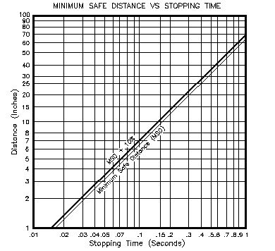
Minimum Safe Distance/Stop Time Readout Board #554700A1A
6-Channel Die Monitor Board #554950A1A
Die Monitor Remote Indicator Board #554955A1A
Crank Position Readout Board #554800A1A
Auxiliary Cam Board (Dry output contact - 120Vac) #554900C1A
Auxiliary Cam Board (Solid state - 12Vdc out) #554900C2A
Auxiliary Cam Board (120Vac) (with 20 pin RC connector) #554900D1A
Auxiliary Cam Board (Solid state) (with 20 pin RC connector) #554900D2A
Auxiliary Cam Power Supply Bd. (for remote cam placement) #552650A1A
External Cam Adjustment Board (for remote front panel adj.) #551275A1A

Replacement Parts: Top

REL 1 – Motor Control Relay ("B" version) 12Vdc coil #500109A1
REL 2 – Motor Forward Relay ("B" version) 120Vac coil #500245A2
Relay hold-down strap (for REL 1 and REL 2 above) #500912A1
MOD 1, 3, 4 – Motor Control/Clutch Output ("D" version) #500249A1
MOD 2 – Motor Forward Input ("D" version) #500248A1
F1 – Time-delay fuse, 4 amp "120Vac" #501201A4
F2 – Time-delay fuse, ¼ amp, "12Vdc Power Supply" #501201A1
F3 – Quick-blow fuse, 1 amp, "Clutch Output" ("B" version) #500012A4
Indicator light bulb, 14.4V, #1813 #262651A1
Indicator light cover, green (POWER ON, GUARD) #501774A3
Indicator light cover, amber (MOTOR ON, CLUTCH ENG.) #501774A2
Indicator light cover, red (Brake/Motion FAULT) #501774A4
Logic-reed contact block, N.O. and N.C. #800TXAR
Logic-reed contact block, N.O. #800TXD1R
Logic-reed contact block, N.C. #800TXD2R
Button mushroom cap, yellow (for ARMING/TOPSTOP) #800TN246Y
Button jumbo mushroom cap, green (for RUN button) #800TN247G
Button jumbo mushroom cap, red (for EMERGENCY STOP) #800TN247R
Standoff, #6-32 x ¾" (Main Control, Aux. Cam Boards) #500876A5
Standoff, #6-32 x 1 ½" (Door Interface Board) #500876A12
1TB – Wire terminal plug, 12 position #1754643
2TB – Wire terminal plug, 16 position ("B" version) #1754724
2TB – Wire terminal plug, 18 position ("D" version) #1754766
Pulse Generator Assembly, with 15' cable ("A2" version) #550750A2
Pulse Generator Assembly, with 15' cable ("B2" version) #550750B2
Single Operator Station Assembly, with standard RUN buttons #555010A1
Single Operator Station Assembly, with Opto-touch RUN buttons #555014A1
Multiple Operator Station Assembly, with keyed ON/OFF selector and light
(requires the Multiple Operator Station Interface Board #554850A1A)
#555011A1


Interconnection Drawings: Top

        The following chart is a list of SYSTEM 4000 Drawings included in the back of the manual, in order of placement. These drawings refer to standard or typical connections for most applications. Customized drawings may have been included with your SYSTEM 4000 per your special application.

Main Control Board component layout ("B" version) #B554100B1
Main Control Board component layout ("D" or "E" version) #B554100D1
2TB (12Vdc) with standard RUN buttons interconnection #B554400D1
2TB (12Vdc) with Opto-touch RUN buttons interconnection #B554400D2
Multiple Press Operator Stations/Multiple Guards Interface #B554851A1
1TB (120Vac) non-reversing motor control interconnection #B554500C1
1TB (120Vac) reversing, slide adjust interconnection #B554500C2
1TB (120Vac) reversing, slide adjust, and lube interconnection #B554500C5
1TB (120Vac) reversing, speed adjust, and lube interconnection #B554500C8
Standard Door Interface 1PL Connections (Prewired at Brandes) #B554600C1
Die Monitor Board Typical Connections #B554950A1
Flywheel brake interface to the SYSTEM 4000 #B576000C1
Safety circuit interface for feed-trip auto-cycling ("B" version) #B554440C1
Progressive die-advance/feed detector sensor interface #B554450C1
Front guarding active in ALL press modes ("B" version) #B554465C1
BAR button installation drawing (typical) #B554470C1
Press-Brake/Stamping Press operation without guarding #B594100C1
Press-Brake/Stamping Press operation with guarding #B594200C1

Top


H&W CONTROLS
A Division of Henry & Wright Corporation
739 East 140th Street - Cleveland, OH 44110
Phone: 216-851-3750 Fax: 216-851-3970

© H&W Controls 2000
All Rights Reserved