| Description | Adjustment |
| Valve/Transducer Assembly Mounting | System 1500 Technical Data |
| System 1500 Wiring |
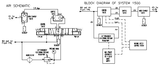
| The System 1500 is used on a multi-slide/four-slide or other similar machine to null the air pressure to the combination clutch/brake unit. Usually between 30 and 40 psi, this null pressure centers the clutch/brake piston between the brake and clutch plates to release the brake, yet not apply the clutch. The slides then can be easily rotated using the hand wheel for setup purposes, without having to turn the motor and flywheel. This system is particularly useful on larger multi-slide presses. |
|
| CAUTION: When used on a multi-slide/four-slide machine or other press or machine with a flywheel and a die-pinch-point, the Valve/Transducer Assembly must be connected to the output of a press or machine clutch/brake safety control system, such as the Brandes - System 2500, to meet OSHA safety regulations. The control valve used is not a press safety valve, and is only intended for continuous-cycling, part-revolution machines. |
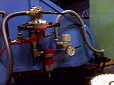
The Valve/Transducer Assembly must be mounted as close to the clutch/brake rotary union as possible to allow quick exhaust and provide the quickest stopping time as possible (3-feet or less). The 3-foot length of hose included can be shortened as required.
The assembly must be mounted with the transducer and micro-air filter in the vertical position. The input air line (at the left side of the control valve) should contain a filter/regulator/lubricator (FRL) unit to prolong the life of the valve assembly, and should be sized according to the valve assembly size used. (The micro-air filter included in the assembly is used only for the transducer.)
Do not attempt to turn or reposition the transducer on the assembly. The transducer will only operate accurately in the installed position.
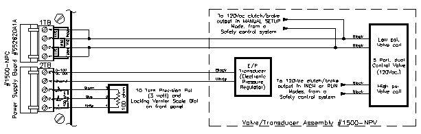
The Valve/Transducer Assembly contains three valves, which must be electrically connected to the Null Pressure Controller and the clutch/brake output of a safety control system as follows...
The white and black wires from the transducer connect directly to the output of the Null Pressure Controller at terminals 2TB 4 and 2TB 5 (black wire to 2TB 5). When included with the System 2500 Multi-Slide Control, the transducer wires connect directly to the output terminals (labeled) in the motor starter box (which are connected to the precision potentiometer on the operator console).
The "A" (low psi) coil of the control valve (terminals 1 and 2) connect to a switch or relay that supplies 115Vac when the null-adjustment (Manual Setup) mode is selected. The "B" (high psi) coil of the control valve must remain off when in the null-adjustment (Manual Setup) mode.
The "B" (high psi) coil of the control valve (terminals 1 and 2) connect to the 115Vac-clutch/brake output of a clutch/brake safety control system, such as the System 2500, which only turns on when initiated in the RUN mode. The "A" (low psi) coil of the control valve should remain off while in the RUN mode.
When using the Null Pressure Controller as a stand-alone system (not interfaced to the System 2500), connect 115Vac or 230Vac to the power input terminals at 1TB 1 through 4, and jumper accordingly. To extend the life of the controller and transducer, this voltage need only be applied when in the null-adjustment (Manual Setup) mode.
The vernier-scale dial is adjusted for the correct "null" air pressure to the combination clutch/brake unit, which will center the piston between the clutch and brake plates to release both the clutch and brake. The "null" air pressure is usually a very close tolerance around 32-35 psi, and depends on the clutch/brake characteristics. Once properly set, selecting the MANUAL SETUP mode will automatically center the piston between the clutch and brake, and enable the hand wheel to be easily rotated. Re-adjustment of the null air pressure may be periodically required as the clutch characteristics change.
Adjustment is done in the MANUAL SETUP mode by increasing the pressure (turning the 11-turn dial clockwise) until the brake just releases. If the motor and flywheel rotate when the hand wheel is rotated, decrease the pressure (counter-clockwise) until the clutch releases. Each full rotation of the dial is equal to 10 psi. The number in the dial "window" is the "tens" digit and the numbers on the dial itself are the "ones" digit. Full range (with 100-psi air pressure input) is 0 to 100 psi, although no more than 40 psi should be required.
A locking lever is located on the side of the dial. The lock must be released (moved up) to adjust the null pressure. Once adjusted, place the lever in the down position to lock the setting, to help stabilize the setting under vibration or if bumped.
|
WARNING: This system shall only be used on machines that operate in a fully guarded mode. The clutch/brake control valve used is NOT a press safety valve, and is only intended for continuous-cycling machines. The installer and machine owner must make sure that all applicable Federal and State OSHA regulations and requirements, and any industry requirements are followed before the machine is put in service. |
H&W
CONTROLS